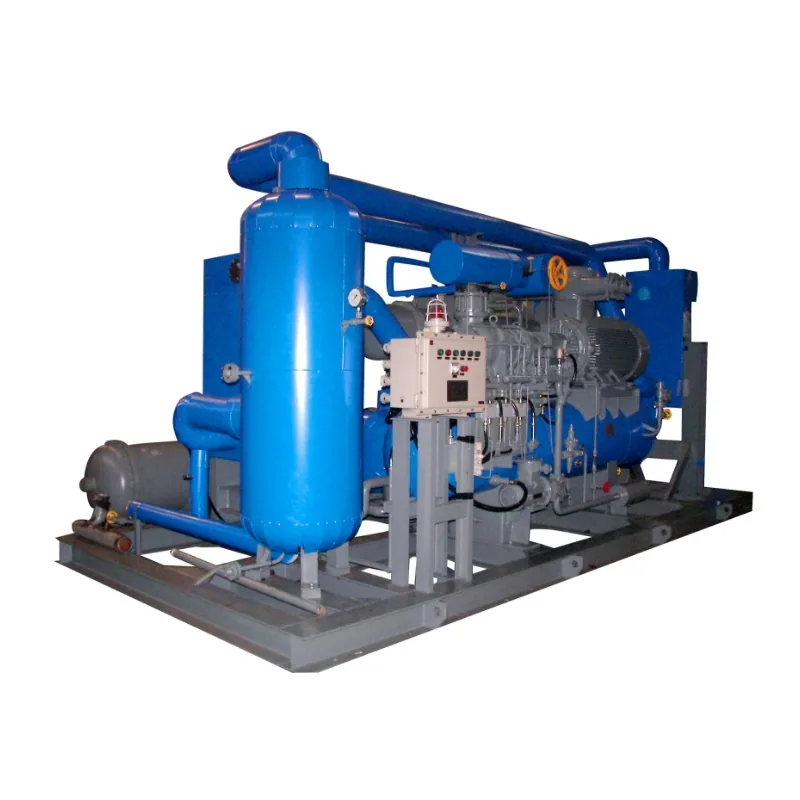
A BOG compressor rarely sees one perfectly steady duty. The data sheet may show a single flow, but the plant has quiet periods, transfer events, start-up conditions, and pressure-control decisions. Then there is the destination. Gas sent to combustion does not automatically have the same outlet requirement as gas returning toward re-liquefaction.
That is why I would delay the model discussion for one meeting. Put the operating cases on the table first. Once everyone agrees about the gas entering the package and the route leaving it, MOON-TECH's published BOG compressor range can be used for a sensible first check.
Begin with a day in the life of the tank
Ask the operations team to describe an actual sequence. The tank is holding. A transfer starts. Flow rises. Later the plant settles again. Which part of that sequence is normal duty, and which part is a short peak?
Write each condition on its own row. Include the source, duration, flow, inlet pressure, and inlet temperature. Composition belongs there too. If an analysis represents only the normal case, label it that way instead of letting it quietly cover every event.
MOON-TECH's published LNG process description says gaseous BOG evaporated from an LNG storage tank can be pressurized for combustion, pipeline transport, or return to the cold box for re-liquefaction. The project may use one of those routes or a different arrangement. Do not tick all three simply because they appear in the product material.
For each route that is genuinely required, add the outlet pressure, outlet temperature, and expected frequency. Who selects the route? What happens when it is unavailable? A few honest blanks are useful at this stage. They tell the team where a decision is still needed.
The Emerson overview of measurement and automation across the LNG value chain gives useful background on the interfaces found around LNG storage and handling. The RFQ still needs to name the particular instruments and boundaries relevant to this package.
Walk to the inlet measurement point
It is surprisingly easy for two people to agree on suction pressure while thinking about different flanges. One means the tank connection. The other means the compressor skid after several upstream items. Put the measurement point on the drawing.
Now look at temperature. Is the stated value measured before or after any conditioning step? Does the lowest value belong to normal running or only to a short event? The supplier needs both the value and its place in the route.
I would keep the inlet discussion practical:
- Show the exact pressure and temperature measurement points.
- State the allowed pressure drop between the source and package.
- Describe the required gas condition at the compressor inlet.
- Name the instruments used before start-up.
- Mark every drain and the owner of its destination.
These lines do not prescribe the equipment. They stop the offer from being based on an imaginary inlet.
Read the published range carefully
MOON-TECH's BOG Compressor information lists inlet pressure from 0 to 0.5 MPa(G) and outlet pressure from 0.5 to 4.5 MPa(G). Inlet temperature is listed above -50°C. Outlet temperature is listed below 50°C when ambient temperature is at or below 40°C. The stated flow-regulation range is 10% to 100%.
The same material lists slide-valve regulation and says variable frequency and slide-valve adjustment can be used in combination.
Those figures belong in the screening column of the comparison sheet. Beside them, make another column for the actual project cases. A case falling inside the published range is a reason to continue the conversation, not a finished selection. Composition, utilities, ambient condition, flow pattern, and the proposed pressure combination still matter to the offered package.
Ask the bidder which row governs selection. If the answer is "the design case," ask for the row number. That small request prevents a lot of later interpretation.
The MOON-TECH BOG compressor route gives the product starting point. If the LNG scheme also includes a refrigeration-loop compressor, open the separate mixed refrigerant compressor route rather than blending the two duties into one equipment line.
Put the process sequence on the wall
MOON-TECH's published BOG Compressor flow shows a BOG heater, inlet buffer tank, filter before the compressor, Stage I compressor, Stage II compressor, oil separator, high-efficiency oil eliminator, after-cooler, and process-gas outlet. Its separate oil circuit runs from the oil separator through the oil cooler, oil filter, and oil pump back to Stage I.
Print that sequence, then mark the offered scope. Perhaps every item is included. Perhaps the project arrangement differs. Either outcome is workable when it is visible.
Take the heater first. Which inlet case is used for the offered duty? What heating medium is assumed? What outlet condition is controlled? Those are bidder questions, not facts to fill in from a generic example.
Move to the buffer tank. Ask what job it performs in the proposed design, what volume is offered, and which pressure or level signals are included. Then check the inlet filter. The quotation should state the basis, pressure-drop allowance, monitoring, and the space needed to remove an element.
Continue through the compression stages and after-cooler. Write the predicted conditions for the agreed cases. Mark where oil separation ends, where drains go, and what gas condition is offered at the outlet. If a sentence says "suitable for downstream use," replace it with the actual handoff requirement.
This wall exercise is not elegant. It works because everyone can see the same missing connection.
Do not let BOG and MR share a data sheet
The acronyms may sit close together on an LNG process diagram, but they describe different duties. MOON-TECH lists its Mixed Refrigerant Screw Compressor Unit for small-scale LNG production, light-hydrocarbon recovery, BOG treatment, and helium recovery.
In the published mixed-refrigerant circuit, low-pressure mixed refrigerant leaves the cold box, is compressed, has oil removed, is cooled, and returns toward the cold box. The published pre-cooling description uses a separate propane circuit with R290, with propane returning in liquid form.
Keep one data sheet for the BOG service and another for the mixed-refrigerant service. If they share utilities or controls, join them with an interface schedule. Do not merge their gas compositions, pressure cases, or destinations into a single table.
Imagine the operator preparing to start one package while the other is unavailable. What permissive is expected? Which signal crosses the cold-box boundary? Can the shared cooling utility support the stated combination? Who supplies the valves and instruments between packages? These are project decisions. A supplier should not have to guess them from a one-line equipment list.
Test the regulation claim against real loads
The published 10% to 100% regulation range will attract attention. The useful next question is how the offered selection addresses the project's load rows.
Take three sticky notes: minimum, normal, and peak. Add a fourth if start-up is different. Ask the bidder to place the proposed control method beside each one. The response should identify the regulation method, assumptions, and stated operating limit for that particular selection.
Do the same for alarms and trips. Rather than requesting a generic list and filing it away, trace one event. If the inlet condition moves outside the agreed case, which measurement sees it? What action follows? Which package receives the signal? Repeat for a cooling problem and an oil-system alarm.
The Emerson control-valve sourcebook for oil and gas service is useful general reading for an instrument and valve review. Actual valve sizing, materials, and control behavior still come from the project specification and the selected equipment.
A table or plot from the bidder is more useful than the word "turndown." It shows where the project cases sit and which assumptions support them.
Give procurement a comparison it can use
By the time quotations arrive, the technical team should have a short, shared package of inputs. One sheet covers gas cases. Another covers utilities and site conditions. A marked process sketch shows the boundary.
The gas sheet needs composition, minimum to maximum flow, any short peak, inlet pressure and temperature, and the required outlet for every selected route. It should also state the measurement points. The utilities sheet can carry the cooling medium, design ambient, power supply, area classification, noise requirement, control-system interface, and available space.
Leave room for maintenance. A compact skid drawing is not enough if an element, cooler part, or service item has no removal path. Ask the bidder to mark those clearances rather than relying on a general note.
On the boundary sketch, assign piping, valves, instruments, relief connections, drains, insulation, and utilities. Then request the alarm and trip deliverables, acceptance cases, and the records expected during testing.
When offers come back, compare exceptions before prices. One supplier may assume a warmer inlet. Another may exclude part of the conditioning sequence. A third may not address the short peak. Put those differences in rows. Technical and commercial reviewers can then discuss the same scope.
A final review at the whiteboard
Before the order, take the selected offer back to the route drawing. Start at the tank-side measurement point. Follow the gas through every included item. Stop at the outlet flange and name the receiving system.
Now repeat the walk for the least comfortable operating row, not just normal load. Does the offered pressure still match the route? Are the utility assumptions the ones available on site? Is the control response described, or merely promised?
Keep the MOON-TECH published conditions in view: inlet pressure from 0 to 0.5 MPa(G), outlet pressure from 0.5 to 4.5 MPa(G), inlet temperature above -50°C, the stated outlet-temperature basis, and regulation from 10% to 100%. Final selection still rests on the actual gas, cases, utilities, and destination.
FAQ
What should go into the first BOG compressor inquiry?
Send the gas analysis, flow cases, inlet pressure and temperature, outlet condition for each route, cooling and site utilities, and a drawing with named measurement points and boundaries.
Which operating conditions does MOON-TECH publish?
The listed inlet range is 0 to 0.5 MPa(G), and the outlet range is 0.5 to 4.5 MPa(G). Inlet temperature is above -50°C. Outlet temperature is below 50°C when ambient temperature is at or below 40°C. The stated regulation range is 10% to 100%.
Must every project use the published process sequence?
No. It is the sequence shown in the MOON-TECH product information. The offered scope and project arrangement should be marked on the actual process sketch.
Why separate BOG and mixed-refrigerant data sheets?
Their gas duties and process routes are different. Separate sheets keep the composition, operating cases, pressure requirements, and controls readable even when both packages are part of one LNG project.
How should low-load performance be compared?
Issue the same minimum, normal, peak, and start-up rows to every bidder. Ask for the proposed regulation method, stated limit, and assumptions against each row.