Capture interface
Define the carbon-rich gas source, composition, pressure, temperature, and contaminants.
Connect captured carbon-rich gas, compressor pressure, heat exchange, refrigeration duty, and the qualified liquid CO2 destination.
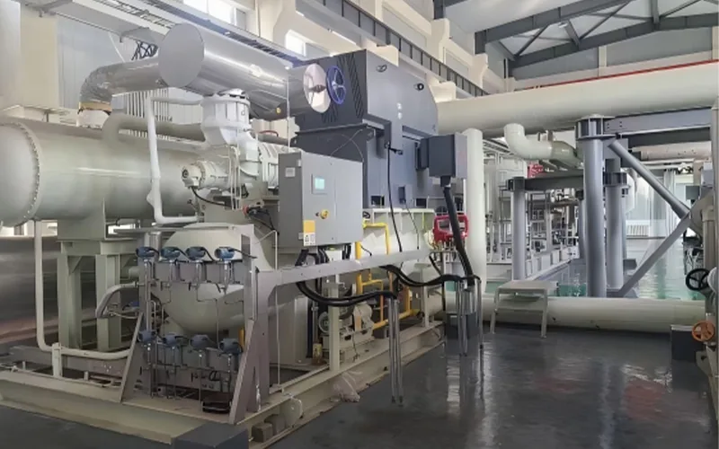
In the approved CCUS process description, captured carbon-rich gas is pressurized by a CO2 compressor to the pressure required for liquefaction.
The gas is liquefied through a heat exchanger, while a refrigeration unit provides the cooling needed for liquefaction.
The approved source does not support a universal purity, energy consumption, liquefaction rate, or transport claim.
Potential liquid CO2 uses are listed as downstream possibilities. They are not a promise that one process configuration meets every quality or regulatory requirement.
Define the carbon-rich gas source, composition, pressure, temperature, and contaminants.
Set the pressure route required for the selected liquefaction process.
Define the heat exchanger and refrigeration duty from actual process data.
Confirm the required liquid quality and the storage, transport, reuse, or sequestration route.
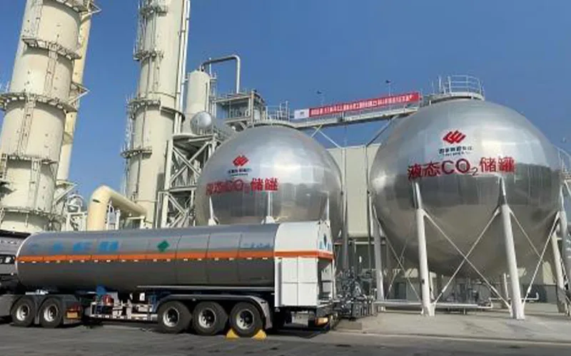
The compressor, heat exchanger, refrigeration system, storage interface, and downstream quality requirement must be checked as one project chain.
The installation image does not establish a universal flow, purity, energy consumption, or project result.
Share the medium, inlet and outlet conditions, target duty, utilities, and project location. The proposal route starts with verified project inputs.